

The tilt and orientation of PV modules shall be optimised to maximise PV system power generation. Typically, PV modules in NSW are optimally placed to achieve the highest year round generation when their inclination is approximately equal to the angle of latitude and facing true north. However, constraints such as available space, building orientation and roof type will place limitations on the placement of PV arrays.
Recommendations below should be followed to maximise solar generation:
PV arrays installed on an easterly or westerly aspect will have vastly reduced power production during evenings and mornings respectively. However, east and/or west facing arrays can provide an alternative system design when there are no suitable space for north facing arrays.
Consider:
Where east and/or west facing PV arrays are proposed, the generation estimates of these systems must show that the system can generate adequate energy to offset power consumption between 9am and 3pm throughout the year, and the economic benefit from this configuration can be justified.
Any proposed PV system must include site specific system energy yield estimates and system costing.
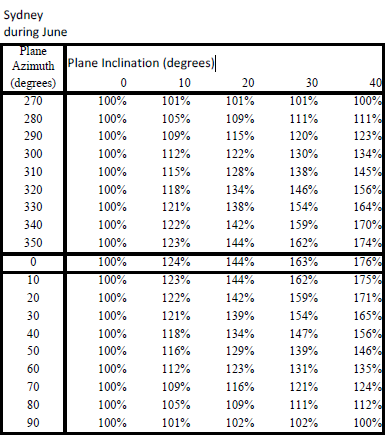
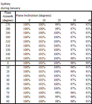
Irradiation data used to calculate power production shall be site specific and take into account the effect of array tilt and orientation. Figure 1 below shows an example of multipliers to apply to horizontal irradiation data to calculate site specific PV generation.
Figure 1. Data table of daily irradiation of Sydney on an inclined plane expressed as percentage of the horizontal value for the months of January and June (CEC, 2013). The plane azimuth indicates the module orientation, and the plane inclination indicates module tilt angle.
System providers may propose PV systems that use micro-inverters (also known as AC systems) or DC Power optimisers. PV systems installed with micro-inverters or DC power optimisers can have higher PV generation when compared to a conventional PV system due to their ability to optimise individual PV module generation and mitigate loss aggregation.
PV systems that utilise this type of equipment do not require all modules in the PV array to have the same tilt and orientation. However, PV modules in these systems should still be oriented and tilted as previously outlined to maximise system output.
A grid-connected PV system should be sized to offset electrical consumption of the installation site to ensure the greatest financial return. The long term value of a PV system’s generation and the cost of the system is not linear, thus proposals for PV system capacity shall be justified by the onsite energy offset and economic benefit on a case by case basis.
The system provider should obtain the existing power bills for the sites where PV systems may be installed. The power bills should indicate the electricity usage and the cost of electricity. Any known electricity tariff changes must be accounted in the financial calculation to increase the accuracy of the optimum system size.
The system provider will need to propose a system size, estimate its generation on the proposed installation site, and estimate the value of the energy offset. The proposal shall include all assumptions used, including price of electricity, system losses and solar insolation data used.
Economic instruments such as simple payback and yearly return on investment rate can be applied to the system cost to evaluate economic viability of proposed PV systems.
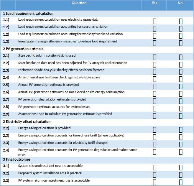
An example checklist is provided below as a guide for preliminary system sizing evaluation.
Inverters have a set range of PV array input voltage and current values within which the inverter can operate safely and efficiently. Matching the array and inverter correctly will reduce the chance of inverter failure and ensure that the system generates the expected energy yield.
It is the PV system designer’s responsibility to ensure that the PV array’s electrical output lies within the inverter’s operating parameters.
As a guide, the capacity rating of a PV array connecting to an inverter should match the inverter’s nominal AC power rating. The PV array capacity rating should not be less than 95% of the inverter’s nominal AC power rating to ensure that the PV array’s electrical characteristics do not easily fall below the inverter’s operating window. For example, if an inverter with a nominal AC power rating of 5kW is used, the PV array’s capacity rating should not be lower than 5kW x 95%, or 4.75kWp.
Oversizing of array is allowed provided that the inverter manufacturer has given written assurance that the inverter is suitable for use in this way and the warranty will not be voided with this application.
Oversizing of array describes the connecting of the inverter to a PV array that has a capacity rating greater than the inverter’s DC input power rating. By oversizing the array, the PV system will produce more power in the morning and evening, and other times of low solar irradiation. Conversely, when solar conditions are favourable, the PV array’s output is ‘clipped’ and the potential energy from the system is lost.
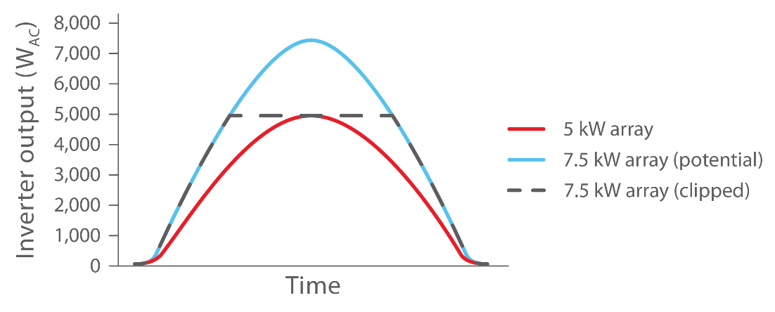
Figure 1. Clipping effect when a 5kW inverter is connected to a 7.5kWp array. The area above the 5kW line represents energy that is not collected by the inverter
Due to the lower cost of PV modules relative to inverters, effective oversizing of the array ensures the value of obtaining more energy per inverter is greater than the value of the potential energy that is not collected.
The CEC’s Grid Connected Solar PV systems – Design guidelines for accredited installers requires the inverter rating to be at least 75% of the PV array capacity rating. For example, if an inverter with a nominal AC power rating of 5kW is used, the maximum PV array size would be 5kW ÷ 75%, i.e. 6.65kWp.
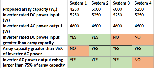
Table 1. Example matching of different sized arrays to a 4.6kW inverter
Table 1 shows four different systems matched to a 4.6kW inverter. Inverter and array are appropriately matched where array capacity is greater than 95% of inverter AC power and inverter AC power output rating is larger than 75% of array capacity.
System 2 and system 3 are acceptable system configurations, where system 3 has an oversized array within the acceptable range. System 1 should consider using an inverter with a lower power rating, and system 4 should consider using an inverter with a higher power rating.
It is of critical importance that care is to be taken to ensure that the PV array’s electrical characteristics are within the inverter’s allowable array size specifications.
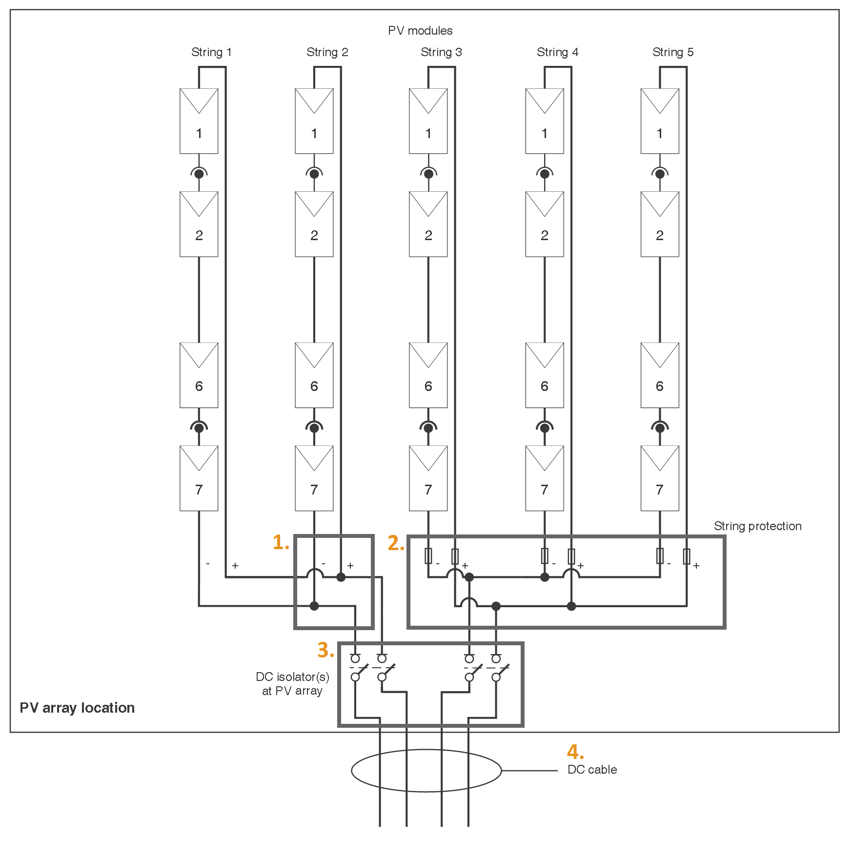
The follow procedure should be used when selecting and installing load breaking DC isolators for PV systems.
Depending on the PV installation characteristics, PV Array DC isolators at the inverter and the array are to be rated to the PV array maximum voltage, either for each positive and negative conductor individually (a per pole voltage rating) or, less commonly, for both positive and negative conductors collectively (an overall voltage rating). In most cases the required current will be 1.25 x the short circuit current (ISC), however AS/NZS 5033:2014 Table 4.2 must be used to confirm the required current rating.
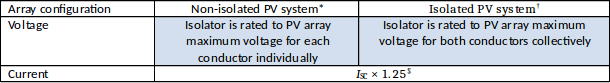
Table 1: Required load breaking DC isolator ratings.
*A non-isolated PV system is a system that has a transformerless inverter.
†An isolated PV system is a system using a transformer inverter.
§Applicable for the majority of systems, but not all. See AS/NZS 5033:2014 Table 4.2 for more information.
NOTE: Systems with functional earthing require the same isolator ratings as non-isolated PV systems.
To calculate the PV array maximum voltage, multiply the PV array open circuit voltage (VOC) by the appropriate correction factor in the following table from AS/NZS 5033:2014 Table 4.1. Use the lowest expected ambient temperature for installation location as the lowest expected operating temperature.
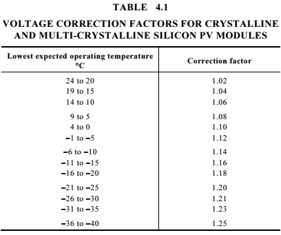
Table 2: Voltage correction factors for calculating the PV array maximum voltage. AS/NZS 5033:2014 Table 4.1
Installing load breaking DC isolators adjacent to the array is a requirement under AS/NZS 5033:2014. In addition to this, load breaking DC isolators are also required at the inverter unless the inverter is within 3 metres of the array and visible from the array. DC isolators exposed to the outdoor environment shall have a minimum ingress protection rating of IP54. If the DC isolator is adjacent to the array then it must have a minimum rating of IP55. Furthermore, enclosures must be installed to the manufacturer’s instructions to maintain their IP rating.
Installation of DC isolator enclosures shall comply with AS/NZS 5033:2014.
Unless otherwise specified by the manufacturer the following installation methods shall be followed.
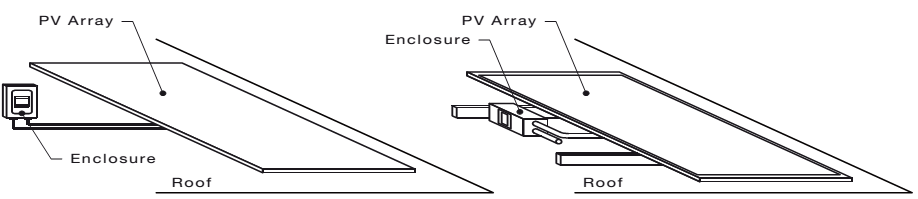
Figure 1: Enclosure orientation from AS/NZS 5033:2014
It is strongly recommended that a sun shield be used to cover the isolator.
Manufacturers’ installation instructions shall be followed to ensure secure installation of PV system to last the expected lifetime of the system. It should also be noted that manufacturers’ ratings and compliance to certain standards will only be achieved by installing PV systems to manufacturers’ specifications.
A PV module’s ability to withstand wind and static load is affected by the attachment area. Manufacturers will specify the clamping area of the module. Clamping of PV modules onto rails must fall within the modules’ specified clamping area to ensure that the modules can withstand loads up to the rated pressure.
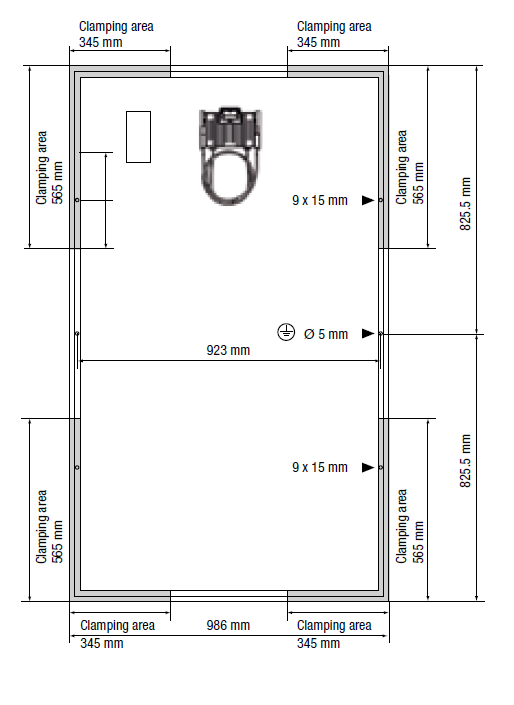
Figure1. PV module clamping zone example: Module dimensions of Clenergy PowerPlus 245M-260M modules showing clamping area in grey.
Mounting systems will only be compliant to AS/NZS1170.2 if the manufacturer has supplied installation instructions certified to AS/NZS1170.2 and these instructions are followed. Care must be taken to ensure the manufacturer’s installation requirements for the specific wind region and terrain category are met, especially:
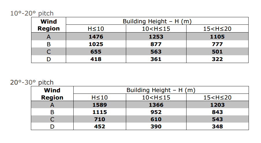
Table 1. Mounting system installation specification example: Clenergy ezRack mounting system installation manual extract showing maximum rail support spacing for tile roofs in terrain category 3
If an installation configuration is not covered by the mounting system manufacturer’s specification, a structural engineer’s certificate must be obtained for the proposed installation configuration, stating the compliance of the proposed installation method with AS/NZS1170.2.
Manufacturer’s installation instructions and corresponding engineer’s certificate must be provided as part of the system documentation.
Inverter station refers to the area where one or more inverters and related equipment are installed. An inverter station is typically located near an electrical distribution cupboard to reduce losses, but can be installed in a designated space within a 1% AC voltage rise margin, and where inverters are protected from exposure to excessive heat, dust and moisture.
Installing inverter station equipment in a clear and logical way can ensure segregation of AC and DC electrical systems and ease of operation for maintenance or safety reasons.
Inverter station equipment includes the following:
Inverter station equipment shall be installed meeting manufacturers’ specified minimum clearance to maintain inverter efficiency and rated lifetime. Where objects are installed within the clearance zone, system owners shall be made aware of the effects of having reduced clearance around inverters and the inverter manufacturer’s declaration, stating that this installation configuration is permitted, shall be included in the system documentation.
Conduits enclosing PV array DC cables shall be installed to AS5033:2014 requirements.
Cables leading up to the inverter shall be secured by saddles so they cannot be inadvertently unplugged from the inverter.
Cable penetration through wall into isolator enclosures shall be sealed to AS3000:2007 requirements to prevent the spread of fire.
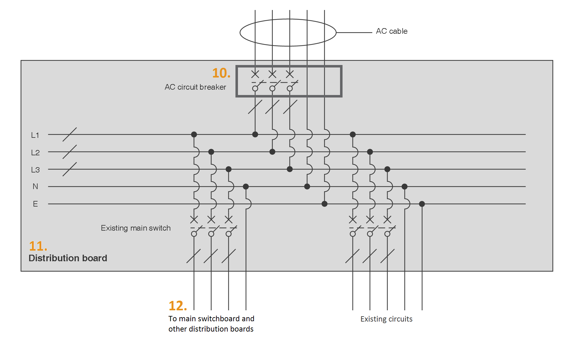
Where multiple inverters are installed at the inverter station, an AC isolator shall be provided for each inverter. Additionally, a single AC isolator should be provided for isolation of all inverters connected to the same electrical distribution cupboard.
Equipment at the inverter station should be arranged as follows:
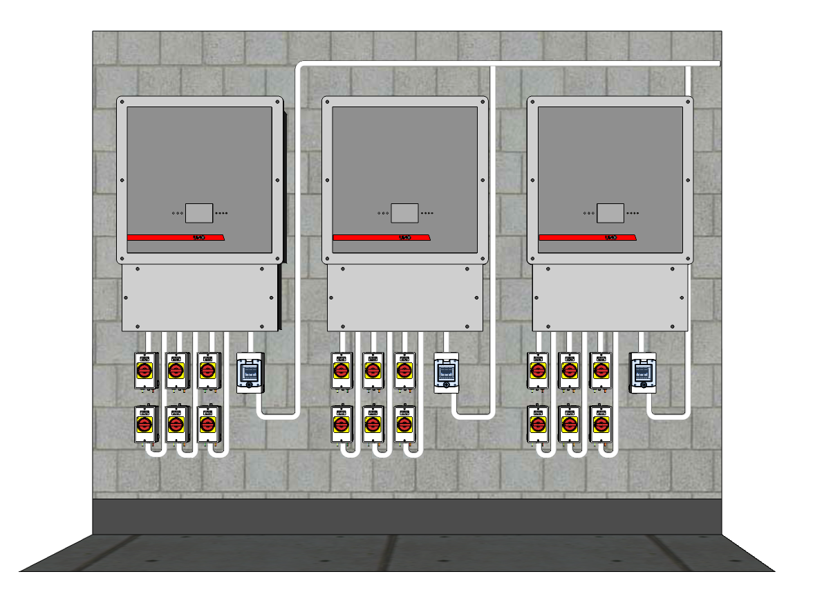
Figure 1. Example configuration of an inverter station. In this example, DC cables enter isolator enclosures from the wall cavity (NOTE: Some inverters may have AC and DC inputs arranged differently to those pictured. The arrangement of protective devices and cable should be adjusted for the location of those inputs)
Installation of PV modules on roofs often require penetration of the roof envelope for affixing the mounting system and for facilitating cable entry. These points of roof penetrations create a potential for water ingress into buildings and electrical systems when they are not correctly installed, which can cause damage to property or a fire hazard. Care must be taken to ensure that roof penetrations are installed correctly to prevent water ingress.
Roof penetration can be classified into two main categories, horizontal penetrations and vertical penetrations. Both categories have their own characteristics and sealing requirement.
Vertical penetrations are made perpendicular to the roofing material. This method is required for metal roofs to facilitate cable entry and mounting foot fixings. Penetration of cables into tiled roofs may also be vertical penetration.
Purpose made flashing and gaskets should be used on vertical penetrations, installed to manufacturer’s specifications.
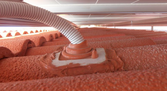
Figure 1. Flashings installed for conduit entry into roof cavity
Where silicon sealants are used, ensure that checking of silicon seals have been included in the maintenance schedule in the system documentation.
Horizontal penetration run through an existing gap between two materials, most commonly between two tiles. This is typically required by tile mounting systems for attaching tile feet to the roof and for cable penetration.
The mounting system must use purpose made tile feet designed for installation via horizontal penetration. Ensure the chosen tile hook is appropriate for the roofing material.
Where allowed by the roof material, grind out top and/or bottom of tiles where needed, to ensure tiles surrounding roof penetrations sit flat. Tile feet must not affect the way roof tiles sit. On brittle tiles where grinding of tiles is not appropriate, large flashing or tile replacements should be used instead of conventional horizontal penetration methods.
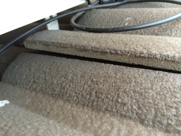
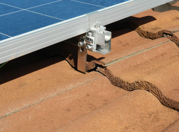
Figure 2. Incorrect installations- tiles lifted by tile hooks
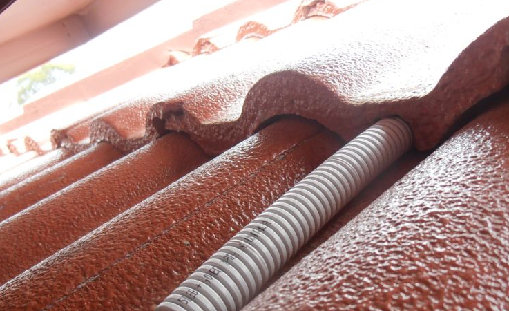
Figure 3. Grinding out tiles at point of penetration to prevent lifting of tiles
Poorly installed conduit at the roof can allow water to enter the conduit at cable entry points or connection points. This can lead to critical failure of the system via water ingress into switch gear or water damage at cable junctions.
Conduit at rooftop should be installed such that:
There is a range of PV system specific signage required according to Australian standards AS/NZS 4777.1:2005 Grid connection of energy systems via inverters and AS/NZS 5033:2014 Installation of PV arrays. Signage requirements can change when these standards are superseded so installers must ensure they are following the most current standards.
Signs are installed to warn emergency crews and tradespeople of the presence of a PV system. Correct signage is required to convey certain system information, to warn of potential electrical danger, and to provide the correct procedure for switching the system off.
The sections below provide an overview of where and what signs are required by Australian standards for a typical grid connect system. The information is not exhaustive and is provided as guidance only; signage requirements for individual sites will differ due to system specific variations including, but not limited to: system configuration, system voltage, equipment used, equipment location, and existing switchboard layouts.
Note that labelling may visually differ from the examples shown. However this is acceptable if the labelling complies with current standards and all additional requirements outlined in EFSG.
|
Location |
Labelling Requirement |
Label example |
|
All PV array and PV array string junction boxes labelled Black on yellow background |
|
|
Combiner box enclosure containing fuses labelled |
|
|
DC isolator enclosure labelled “PV ARRAY D.C. ISOLATOR” |
|
|
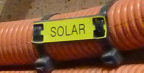
Wiring enclosure labelled “SOLAR” every 2 metres and visible after mounting
|
|
|
Location |
Labelling Requirement |
Label example |
|
Enclosure labelled “PV ARRAY D.C. ISOLATOR” |
|
|
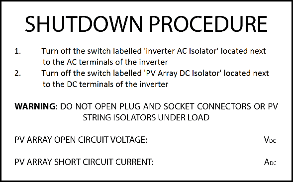
Shutdown procedure Ensure that the descriptions in the procedure match the labels on the isolators to which they are referring. |
|
|
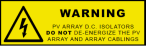
“WARNING: PV ARRAY D.C. ISOLATORS DO NOT DE-ENERGIZE THE PV ARRAY AND ARRAY CABLING” Black lettering on a yellow background. |
||
|
Install where multiple DC isolators are connected to inverter: “WARNING: MULTIPLE D.C. SOURCES TURN OFF ALL D.C. ISOLATORS TO ISOLATE EQUIPMENT” Black lettering on a yellow background. |
||
|
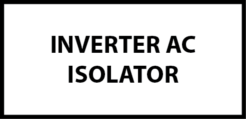
Labelling that matches shutdown procedure ‘Inverter A.C. Isolator’ or similar |
|
|
Install sign “Do not switch off power supply” on PV system monitoring device/s |
|
|
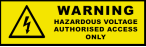
Where system voltage exceeds 600V DC, install sign: WARNING HAZARDOUS VOLTAGE AUTHORIZED ACCESS ONLY Black lettering on a yellow background. |
|
|
Location |
Labelling Requirement |
Label example |
|
“INVERTER SUPPLY MAIN SWITCH” or similar |
|
|
Shutdown procedure: Ensure that the descriptions in the procedure match the labels on the isolators to which they are referring. |
|
|
“WARNING: PV ARRAY D.C. ISOLATORS DO NOT DE-ENERGIZE THE PV ARRAY AND ARRAY CABLING” Black lettering on a yellow background. |
|
|
|
“Warning dual supply isolate normal and inverter supply before working on this switchboard” sign provided in the distribution board. |
|
|
|
12.1 Main switchboard and meter board |
Label grid supply “NORMAL SUPPLY MAIN SWITCH” or similar |
|
|
Fire emergency information sign as per AS5033:2014 requirements |
|
|
|
Sign displaying location of distribution board to which inverter supply is connected as per AS4777.1 requirements. |
|
|
|
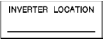
Sign indicating Inverter location |
|
|
|
Circular green reflector sign at least 70 mm in diameter displaying the letters ‘PV’ installed on exterior of switchboard and visible on approach |
|
|
|
|
|
|
|
12.2 Other distribution boards |
Sign displaying location of distribution board to which inverter supply is connected as per AS4777.1 requirements (Required on boards not directly connected to the inverter) |
|
1 PV system monitoring devices may be placed in distribution boards. Same signage rules will still apply